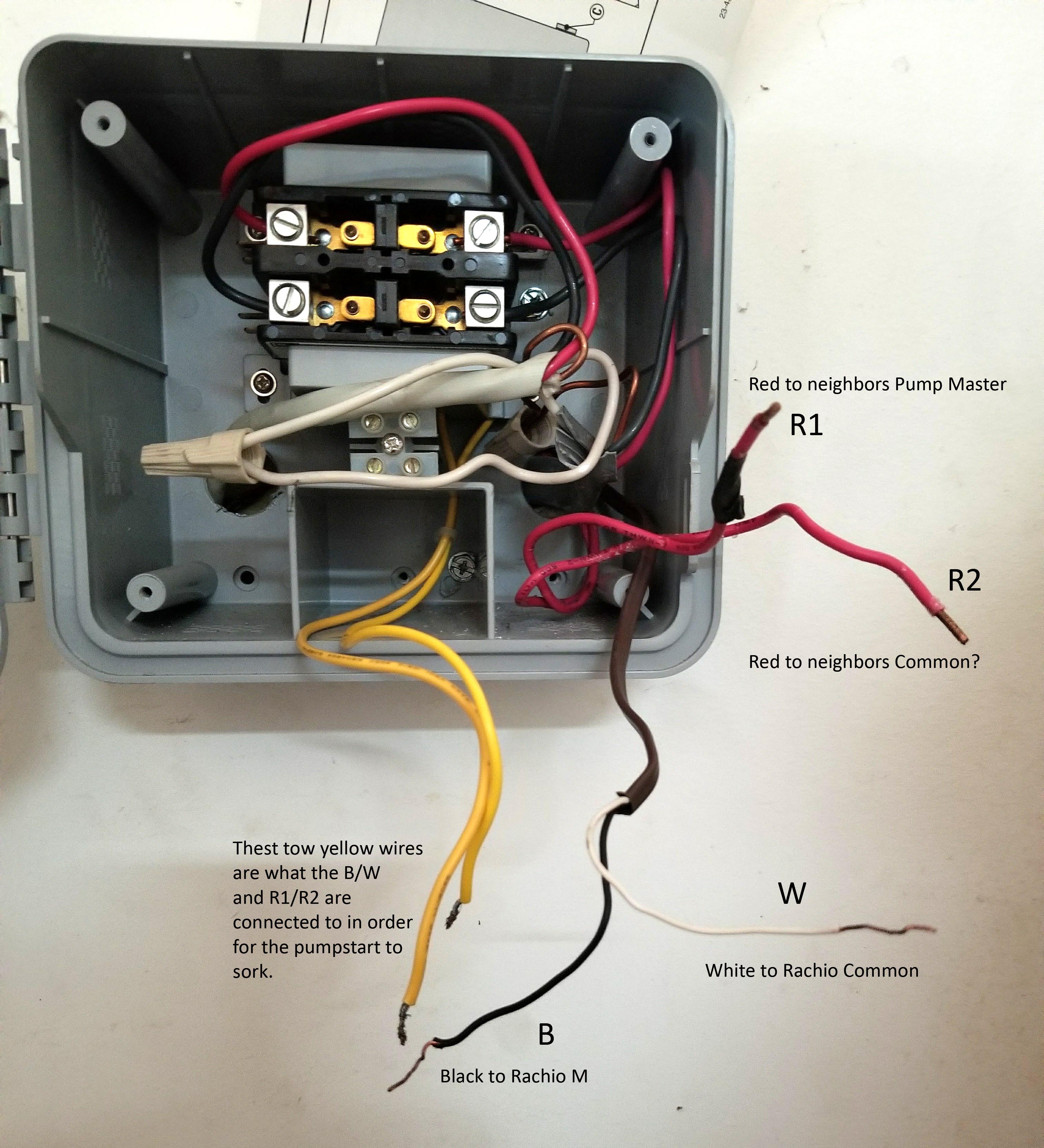
Have you ever found yourself facing a daunting electrical project, staring at a jumble of wires and wondering where to begin? I know the feeling. I recently had to replace my well pump’s start relay, and let me tell you, deciphering the wiring diagram felt like trying to solve a cryptic puzzle. But with some careful research and a methodical approach, I managed to tackle the job successfully. In this article, we’ll delve into the intricacies of a Hunter pump start relay wiring diagram, breaking down the process into manageable steps, so you can confidently tackle your own repair.

Image: mobinspire.blogspot.com
From understanding the components to identifying the correct wires, we’ll cover everything you need to know about this critical part of your well pump system. So grab your tools, put on your thinking cap, and get ready to learn how to master the Hunter pump start relay wiring diagram.
Understanding the Hunter Pump Start Relay
The Hunter pump start relay serves as a vital intermediary between the well pump motor and the control system. It’s a small, but crucial device that plays a critical role in starting and stopping your pump. Imagine it like a traffic cop for your well pump. It acts as a switch, responding to signals from the control system to either energize the pump motor (allowing it to run) or deactivate it (turning the pump off).
The Hunter start relay comes equipped with multiple terminals, each corresponding to a specific part of the well pump system:
- Power terminals: These terminals (typically labeled ‘L’ and ‘N’) receive the power supply from the electrical source, typically a circuit breaker in your electrical panel.
- Control terminals: These terminals (usually designated ‘C’ and ‘NC’ or ‘NO’) connect to the well pump control system, such as a pressure switch or float switch. The control system sends signals to these terminals, telling the start relay to energize or de-energize the pump.
- Motor terminals: These terminals (labeled ‘M’ and ‘P’ or ‘S’ and ‘T’) connect directly to the pump motor itself, providing the power needed to make the motor spin.
The Hunter start relay wiring diagrams usually depict these terminals and how they connect to the different components in the well system. It’s a bit like a roadmap for your electrical journey, guiding you from the power source to the pump motor.
Decoding the Hunter Pump Start Relay Wiring Diagram
For a successful wiring job, a clear understanding of the start relay wiring diagram is essential. These diagrams usually display a symbolic representation of the components and the way they connect. Here’s how to navigate the symbols and understand their meaning:
- Power source: Typically represented by a circle with a “P” inside, indicating the primary source of electricity for the system.
- Control system: Symbolized by a rectangular box, often labeled with its specific type, such as “Pressure Switch” or “Float Switch.”
- Motor: Generally depicted as a motor icon, with a circular outer ring representing the casing, and an inner section symbolizing the rotor (the spinning part of the motor).
- Start relay: Shown as a square box or an elongated rectangle labeled “Start Relay”. The terminals are indicated as points on this box.
- Wires: Connecting lines represent the electrical wiring. These lines may be labeled with letters corresponding to the specific terminals on the components.
With practice and a little patience, reading these diagrams becomes clear and manageable. It’s like learning a new language, with the symbols serving as the alphabet of your well-pump wiring system.
Connecting the Wires: A Step-by-Step Guide
Once you’ve familiarized yourself with the diagram, it’s time to connect the wires. Here’s a step-by-step guide that will walk you through the process:
- Identify the wires: Match the colors or labels on the wires to the corresponding terminals on the diagram. For example, the red wire might go to the ‘L’ terminal (for ‘Line’), representing the live wire from the power source.
- Connect the power wires: Attach the ‘L’ wire from the power source to the ‘L’ terminal on the start relay, and connect the ‘N’ wire (neutral) to the ‘N’ terminal on the start relay.
- Connect the control wires: Connect the wires from the control system (such as the pressure switch) to the ‘C’, ‘NC’, or ‘NO’ terminals on the start relay, based on the instructions specific for your control system.
- Connect the motor wires: Attach the wires from the motor to the ‘M’ and ‘P’, or ‘S’ and ‘T’ terminals on the start relay. Make sure to connect these wires correctly based on the diagram.
- Secure the connections: Tighten all screw connections to ensure a secure contact, preventing potential issues due to loose connections.
- Test the connections: After making all connections, thoroughly test the system by turning the power on and verifying that the pump starts and stops as expected. Carefully monitor for any signs of overheating or malfunctioning.

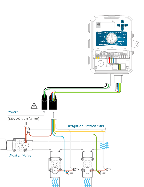
Image: www.hunterindustries.com
Troubleshooting Tips: Common Wiring Issues
Even with careful wiring, sometimes unexpected problems can arise. Here are some of the most common wiring issues and how to troubleshoot them:
- No power: If the pump doesn’t turn on, start by checking the circuit breaker to ensure it is switched on. If the circuit breaker is tripped, there might be a short circuit or overload in the system. If the breaker is on, check the wires connected to the power terminals (L and N) of the start relay. A loose connection could be the culprit.
- Pump running constantly: If the pump continuously runs without stopping, it might indicate a malfunctioning control switch, such as a stuck pressure switch. Check the connections to the control terminals (C, NC, or NO) and ensure the switch is functioning correctly.
- Pump not starting: If the pump isn’t starting, inspect the wiring connection to the motor terminals (M and P or S and T). A loose connection or a broken wire could prevent power from reaching the motor. Also, examine the start relay itself for any signs of damage or overheating.
Always shut off the power before attempting to troubleshoot or make any repairs in the wiring system. If you’re unsure about any aspect of the wiring process, it’s best to consult a certified electrician to ensure your safety and the integrity of the system.
FAQ
Here are answers to some frequently asked questions about Hunter pump start relay wiring diagrams:
Q1: Where can I find a Hunter pump start relay wiring diagram?
A: Wiring diagrams are often supplied with the start relay or the well pump system. You can also find them online by searching for “Hunter pump start relay wiring diagram” or by contacting Hunter customer support.
Q2: What does it mean if a wire is labeled ‘NO’, ‘NC’, or ‘C’?
A: These labels refer to the type of contact within the control system. ‘NO’ stands for “Normally Open,” meaning the circuit is open (no electricity flowing) until a signal triggers it to close. ‘NC’ represents “Normally Closed,” meaning the circuit is closed (electricity flowing) until a signal triggers it to open. ‘C’ indicates the common terminal, where the wire from the control system initiates the command to activate or deactivate the relay.
Q3: Can I use any start relay for my well pump?
A: No, it’s essential to use a start relay specifically designed for the voltage and amperage requirements of your well pump motor. Using an incompatible relay can lead to damage or malfunction of the system.
Q4: Can I modify the wiring diagram?
A: Modifying the wiring diagram without proper knowledge and expertise can be extremely dangerous. It’s best to follow the original diagram provided by the manufacturer, consulting an electrician if you need clarification or adjustments.
Hunter Pump Start Relay Wiring Diagram
Conclusion: Mastering the Hunter Pump Start Relay Wiring Diagram
Understanding the Hunter pump start relay wiring diagram is a key skill for any homeowner or DIY enthusiast. By following the step-by-step guide and troubleshooting tips provided in this article, you’ll be equipped to confidently handle your well pump’s electrical system. Remember, safety is paramount. Always shut off the power before working on electrical components, and consult a professional electrician if you’re unsure about any aspect of the process.
Now that you’ve learned the ins and outs of Hunter pump start relay wiring diagrams, are you ready to tackle your own wiring project?


